Retrofitting a Conventional Fan with Remote Control
From hacking the control board to integrating with Home Assistant
In the middle of the summer heat wave of 2022, my trusty old fan of 15+ years finally gave out on me. Despite my best efforts, I wasn't able to fix it, so I made my way to the hardware store to pick up a replacement. Given the high demand for fans, my options were limited, so I ended up picking a relatively basic model: A TV 45-100 Tower Fan.
As a dedicated tinkerer, I wasn't content with leaving the fan as it was. I aimed to integrate it into my home automation system, allowing me to automatically turn it on whenever the temperature rose too high. Not to mention, my feline friends enjoy the breeze even when I'm away.
The solution presented itself in the form of a ESP8266 Wi-Fi MCU board with some custom firmware.
The User Interface
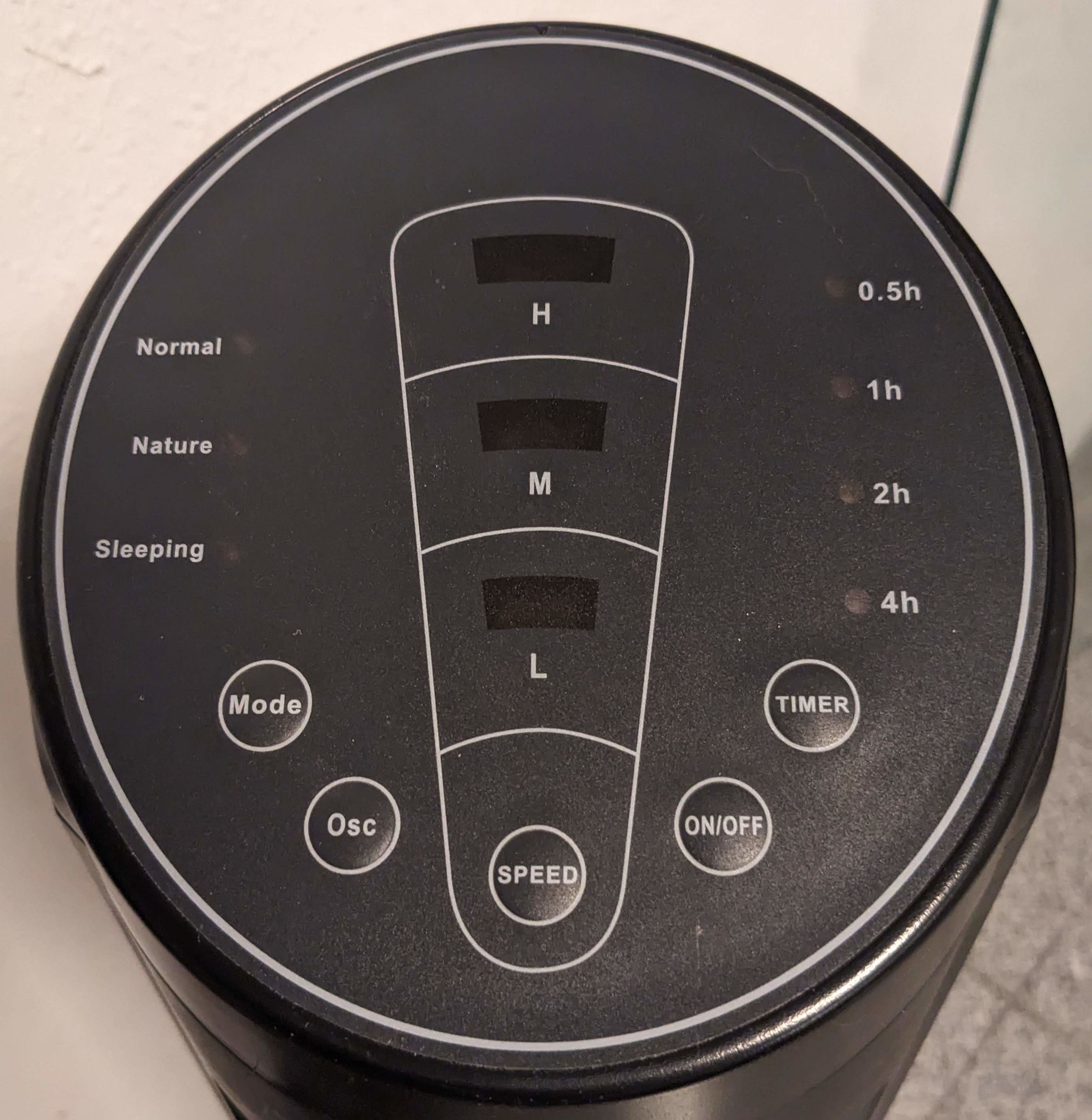
The fan controls are pretty basic. Most buttons just cycle through their states, starting from the default and wrapping around. The TIMER button is a bit more complicated. It is a binary counter that can be set to any value between 0.5 and 7.5 hours, but is only indicated by 4 LEDs, the sum of which gives the total amount of time. The ON/OFF and Osc (Oscillation) buttons don't have any LEDs to indicate status, although it is typically easy to discern their activation from the resulting fan behavior.
| Button | States |
|---|---|
| ON/OFF | Either off(default) or on |
| SPEED | One of L(default), M or H |
| Mode | One of Normal(default), Nature or Sleeping |
| Osc | Either off(default) or on |
| TIMER | Any of 0.5h, 1h, 2h and 4h, including none(default) |
Reverse-Engineering the Control Board
First things first, I opened the chassis and had a look at the control board. I carefully poked around a bit with a multimeter and attached some test leads to anything that looked important. Then I took a look at the signals with a basic handheld oscilloscope to make sure that I don't blow up my bench oscilloscope poking around in a mains circuit.
Conveniently, the board runs its control logic at 5 V, so it seems that I will be able to directly interface with it using common microcontrollers. Although they mostly run at 3.3 V, they often also tolerate 5 V just fine.
Status LEDs
In order to gain a better understanding of the fan's status LED control mechanism, I took a closer look at the connections between the microcontroller and the LEDs. By creating a basic circuit diagram, I was able to visualize the interplay between the various LEDs.
As you can see, there are more LEDs than control pins, so there must be some kind of multiplexing going on. Some pins are connected to common anodes (An) of multiple LEDs, while others are connected to common cathodes (Kn).
This means that there are three possible states for each LED, depending on the voltage levels:
- Anode
HIGHand cathodeLOW: LED on - Anode
LOWand cathodeHIGH: LED off, because the diode will block the reverse flow of current - Anode and cathode at the same voltage level: LED off, because there is no potential difference across the diode
This table shows the possible combinations of voltage levels for each LED to be on, based on the diagram (Figure 3):
| LED | A1 | A2 | K1 | K2 | K3 | K4 | K5 |
|---|---|---|---|---|---|---|---|
| Normal | HIGH | LOW | |||||
| Nature | HIGH | LOW | |||||
| Sleeping | HIGH | LOW | |||||
| H | HIGH | LOW | |||||
| M | HIGH | LOW | |||||
| L | HIGH | LOW | |||||
| 0.5h | HIGH | LOW | |||||
| 1h | HIGH | LOW | |||||
| 2h | HIGH | LOW | |||||
| 4h | HIGH | LOW |
It's important to note that the anodes in the circuit are active high, while the cathodes are active low. The inverted active state is indicated by the bar over Kn in the diagram (Figure 3). For a given LED to turn on, both the anode and cathode must be in an active state. For example, to turn on the Normal LED, we need to pull A1 HIGH and K1 LOW.
To keep other LEDs from turning on at the same time, we need to set their pins to the opposite of their active state. For instance, to keep the Nature LED from turning on at the same time as the Normal LED, we need to keep A2 LOW.
For example, to turn on the Normal and H LEDs, while keeping all the other ones off, we need all the pins in this state:
| Pin | State | Voltage Level |
|---|---|---|
| A1 | Active | HIGH |
| A2 | Inactive | LOW |
| K1 | Active | LOW |
| K2 | Active | LOW |
| K3 | Inactive | HIGH |
| K4 | Inactive | HIGH |
| K5 | Inactive | HIGH |
By reading the current state of the status LEDs, we are able to figure out most of the fan's current state:
- Is it in Normal, Nature, or Sleeping mode?
- Which speed is it running at?
- Which time is the timer set to?
And if any of the LEDs are on, we know if the fan is powered on at all.
Oscillation
Since oscillation doesn't have any status LEDs, we need to detect it some other way. After some more multimeter poking around, I found the pin that controls the oscillation motor. It seems to be a PWM (pulse-width modulated) signal, but we only care if it's happening at all, since the fan doesn't actually have multiple oscillation speeds.
Buttons
The face panel push buttons just short two pins together.
Interfacing with the Control Board
After understanding the fan's workings, the next step was to prototype a reliable method for reading the current state and controlling it accordingly.
Reading Status LEDs
Unfortunately, my initial approach of reading the voltage levels on the status LED pins according to Table 2 turned out to be unsuccessful. The control signal is modulated by PWM in addition to everything else, which resulted in very messy readings. Getting reliable data would likely have required an exposed clock signal to time my reads, which didn't seem to exist.
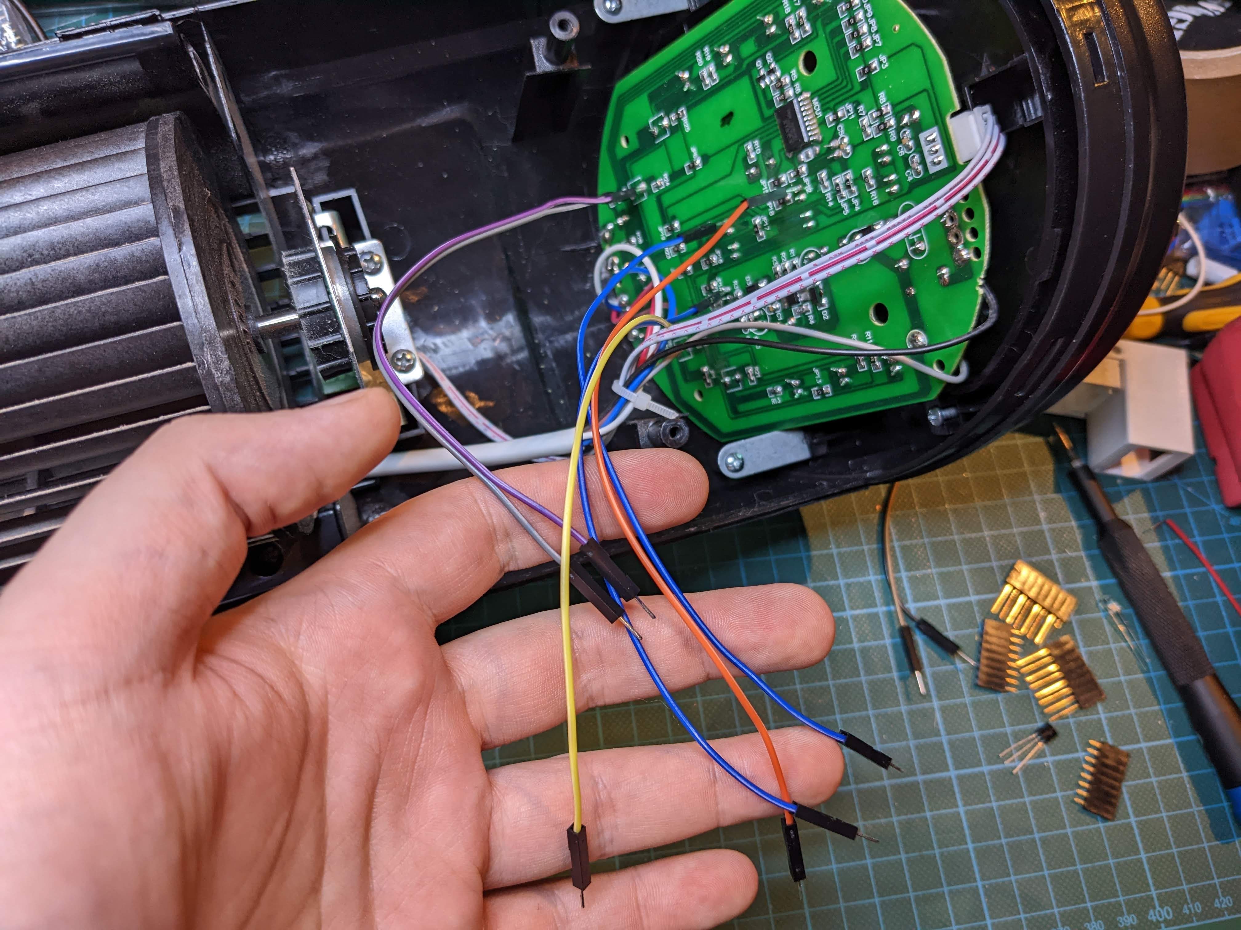
This might have still been possible to do using some additional hardware, but I decided to go with a simpler (and cheaper) approach: Photoresistors.
To mount the photoresistors, I designed some 3D-printed shrouds that attach to the LEDs and have a hole on the side to insert a photoresistor into.
They were printed in black PLA, in order to absorb most indirect sources of light to make the readings more reliable. I then hot glued them to the control board, inserted the photoresistors, and glued those in place too.
I then wired up one lead of each photoresistor to the 5 V power rail of the fan, and the other lead to a ribbon cable going to the microcontroller to read later.
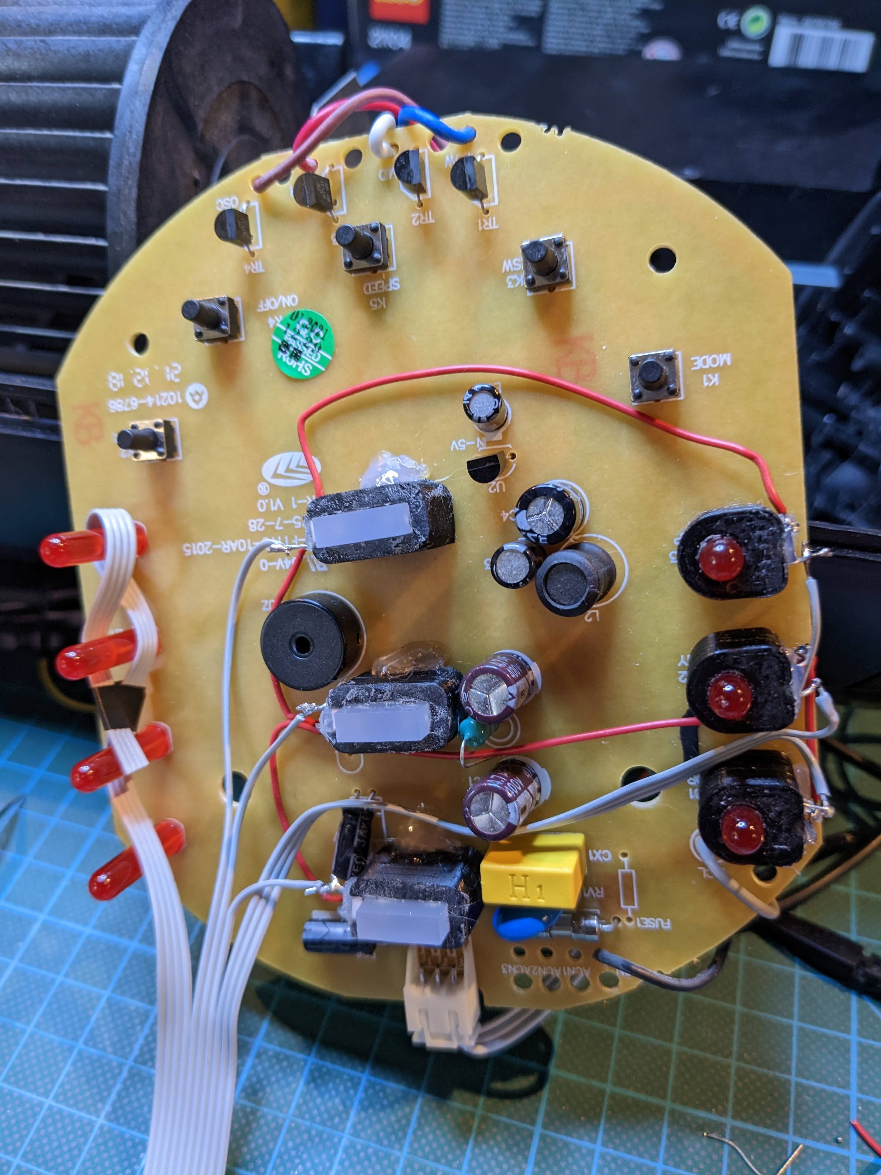
You might have noticed that I didn't bother wiring up the timer LEDs. This is because I wasn't actually interested in that feature. Any scheduling I might want to do was going to happen in Home Assistant anyway, in addition to just being significantly more powerful.
I did run the cables anyway, just in case I ever wanted to add that functionality in the future.
Of course, reading the LEDs this way would bring other challenges. The LEDs are exposed on the front plate, so varying ambient light levels could skew the readings. I decided to deal with this problem in firmware.
Detecting Oscillation
In this case, we only care whether it is happening at all, rather than the exact speed. However, since this is also a PWM signal, it can temporarily read LOW even when oscillation is active. So if we read it at the wrong instant, we might get a false negative.
A simple way to deal with this is to add a capacitor to the circuit to smooth out the signal to an average voltage. But if we do that, the signal will no longer be PWM and the motor won't work correctly.
This can be solved by isolating the measuring circuit from the rest of the fan circuit, for example, by using an op amp (operational amplifier). This way, the original signal isn't affected by the smoothing capacitor behind it.
Pushing Buttons
The easiest way to change the state is to just push the buttons on the face panel. This is done by shorting two pins together with a transistor across each push button. They are also wired up using a ribbon cable to the microcontroller.
Making the Bridge
With all of these methods tested, it was time to design the circuit for integrating with my home network. Here are the requirements:
- Wi-Fi connectivity
- 1 input pin for reading the oscillation signal
- 3 input pins for reading the Mode photoresistors
- 3 input pins for reading the SPEED photoresistors
- 4 input pins for reading the TIMER photoresistors
- 5 output pins for "pushing" the face panel buttons
An ESP8266 is a great choice for this, because it is cheap and has an integrated Wi-Fi antenna. Unfortunately, it doesn't have enough pins. Additionally, not all the pins are created equal1, so they might already have a secondary purpose that makes them unsuitable for our particular use-case. So we will need to use a multiplexer to share some pins.
Here is the circuit I came up with:
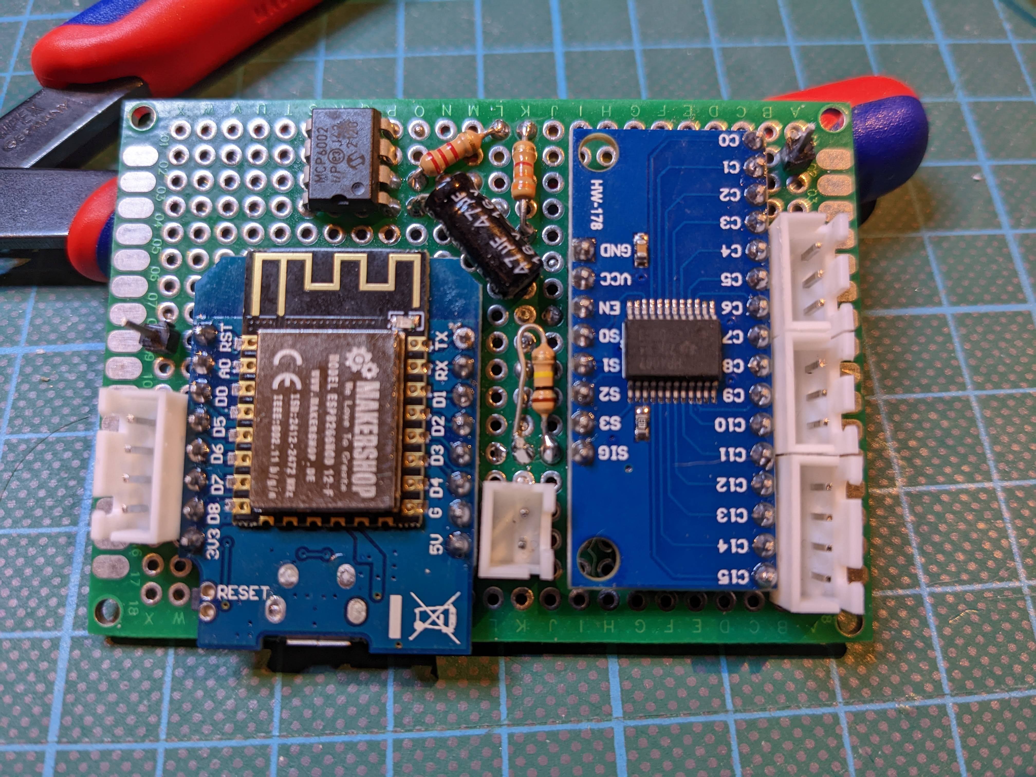
This design uses an ESP8266-based D1 Mini clone as the brains and Wi-Fi module, and a CD74HC4067 breakout board to multiplex the inputs.
Pin D1 is used to control the power button (OUT_PWR), because it does not go HIGH during boot, which would otherwise turn on the fan accidentally. This does not matter for any other output pins, because they don't do anything while the fan is still turned off.
Pins D5, D6, D7 and D8 control the other four face buttons (OUT_CTRL).
Pins D0, D2, D3 and D4 set the address of the input multiplexer, whose signal will be read through the analog A0 pin. Using an analog pin affords the firmware a lot of flexibility in how to interpret the incoming data, especially when dealing with values that need to be calibrated. A0 also has a pull-down resistor that ensures we always read LOW when the multiplexer is set to an unused address.
The oscillation signal (IN_OSC) is isolated through a MCP6001 op amp in a buffer configuration, stepped down from 5 V to 3.3 V using a voltage divider, and smoothed using a capacitor before passing through the input multiplexer like all the other input signals.
The incoming signals for IN_MODE, IN_SPEED and IN_TIMER don't need to be stepped down, because the photoresistors they are attached to already drop the voltage by enough on their own to not clip the signal at 3.3 V.
The input signals are attached to the multiplexer in a way where the upper two bits of the address are used to select one of the input types (IN_OSC, IN_MODE, IN_SPEED or IN_TIMER), and the lower two bits are used to select a single input of that type (IN_OSC has only one input, IN_MODE has three, IN_SPEED has three and IN_TIMER has four), starting at the lowest pin of that address range.
The whole bridge board will be powered off of the 5 V power rail of the fan control board and share a common ground.
With the schematic done, it was time to figure out the component arrangement:
Note that I replaced the MCP6001 with an MCP6002, which is just a dual version of the same op amp that I already had on hand.
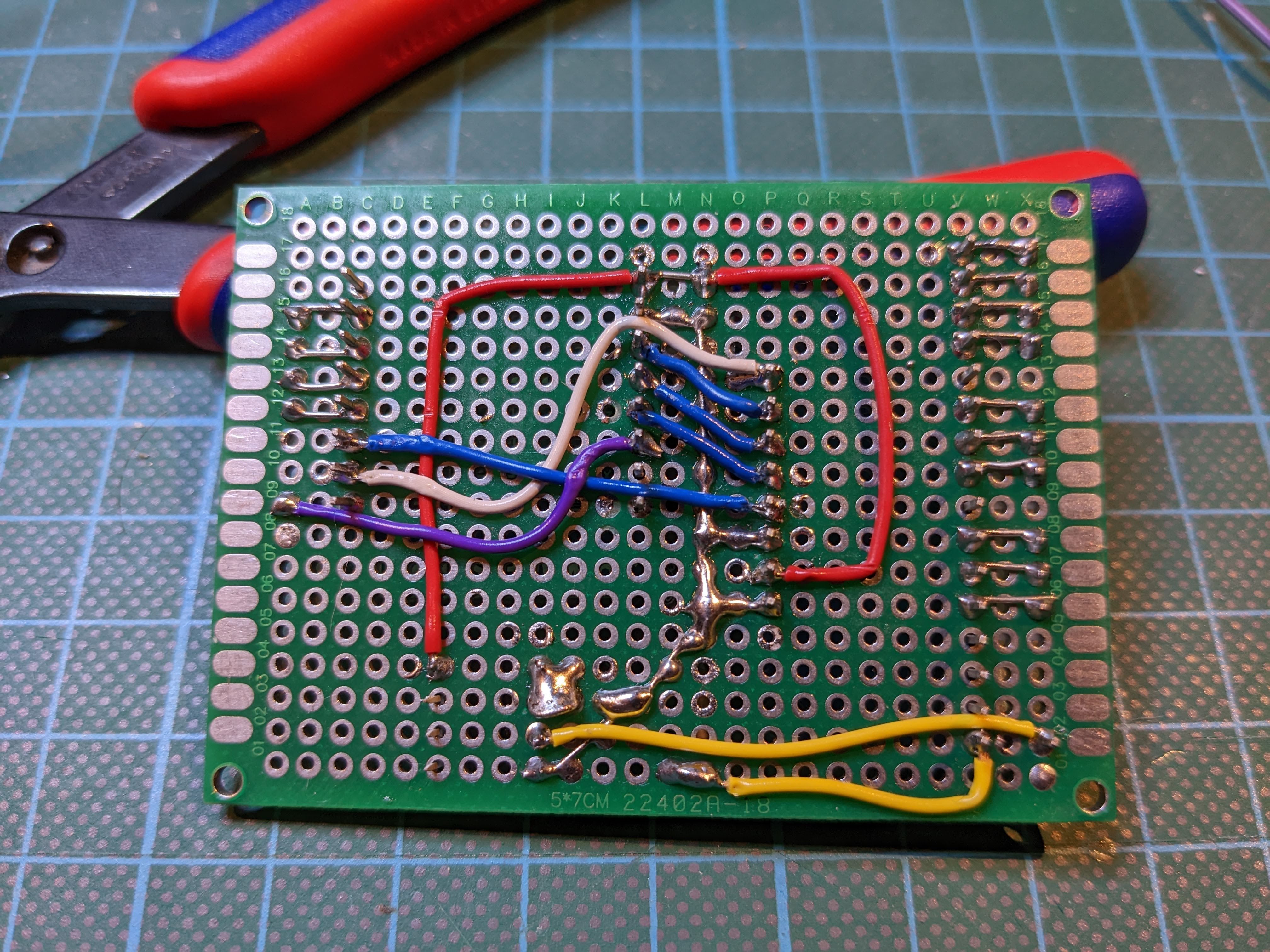
I wasn't going to have this board manufactured as a one-off, but I based the key dimensions on some perfboard I had, so it was still useful as a template for the soldering process. The connections are laid out to be relatively short to keep soldering reasonably simple.
Here is what the final board looks like:
And here is how it attaches to the fan control board using a simple 3D-printed bracket, some screws and cables.
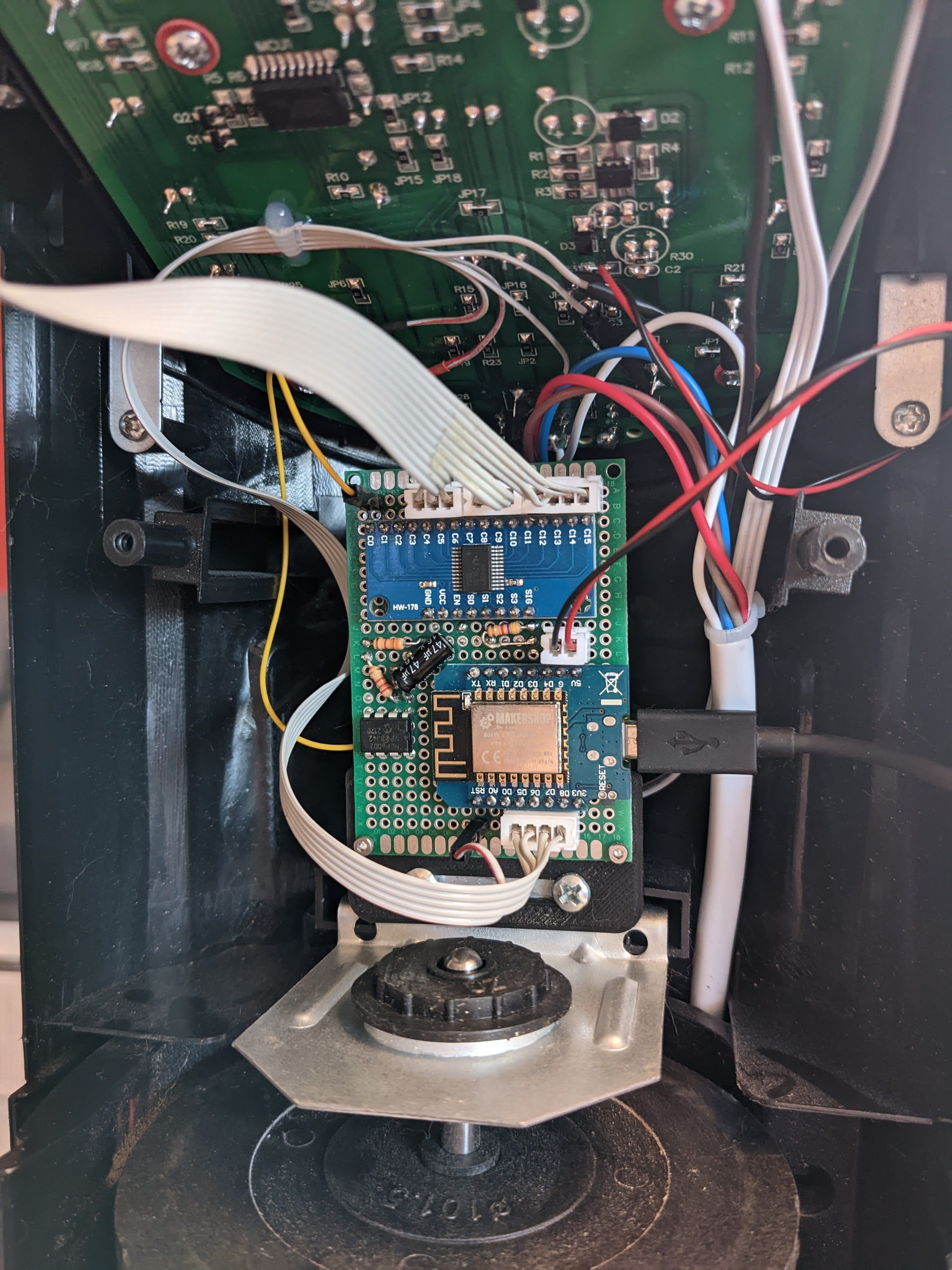
The black and red cable pair is attached to the 5 V power rail and ground of the fan control board, respectively. The yellow cable leads to the oscillation signal, the upper ribbon cable leads to the status LED photoresistors (Figure 6), and the bottom ribbon cable leads to the face panel buttons.
Firmware
The firmware is written in relatively low-level C/C++, using the PlatformIO toolchain for compilation.
As soon as the fan is plugged in, the bridge will power up, connect to Wi-Fi and an MQTT broker using the supplied credentials, and begin continuously monitoring the current state.
Detecting the Current State
The first step is to cycle through the input multiplexer and read several samples from each input through A0, and calculate their average to reduce noise. The ADC (analog-to-digital converter) on the ESP8266 has a resolution of 10 bits, which means it can read 210 (1024) discrete values between 0 V and 3.3 V.
SPEED and Mode detection work like this:
- If any of the LEDs read significantly higher than the others, assume it is the active one
- If all the LEDs are within a certain threshold of each other, assume it is inactive (e.g. off)
- In all other cases, mark the state as indeterminate due to insufficient confidence
For my initial testing I set the thresholds to 100, which means that if the difference between the highest and lowest input value is less than 100, the input is considered inactive, and if one of the LEDs reads at least 100 higher than the other ones in the same group, the input is considered active.
If SPEED and Mode are both determined to be currently active, we can assume that the fan is almost certainly powered on. If both are inactive, we can assume that the fan is powered off. If they don't agree, the power state is indeterminate, and we will have to wait for more determinate input readings.
The oscillation signal is also interpreted using a threshold to determine whether the fan is currently oscillating or not. In my case a value of 740 seems to produce quite reliable results.
Once the current state has been determined, the bridge will publish all changes to the MQTT broker, using values that are designed to integrate well with Home Assistant2.
| Topic | Values |
|---|---|
state | online when connected, offline when disconnected |
state/power | ON or OFF, None when indeterminate |
state/speed | 0, 1, 2 or 3, None when indeterminate |
state/mode | Normal, Nature or Sleeping, None when off or indeterminate |
state/oscillation | ON or OFF, None when indeterminate |
Programmatically Changing the State
The bridge will listen on the following MQTT command topics to change the state of the fan:
| Topic | Accepted Values |
|---|---|
command/power | ON or OFF |
command/speed | ON, OFF, 0, 1, 2 or 3 |
command/mode | ON, OFF, Normal, Nature or Sleeping |
command/oscillation | ON or OFF |
Sending anything but OFF or 0 to these topics will imply powering on the fan. For example, sending ON to command/speed will turn on the fan and set the speed to the default.
Similarly, sending OFF to command/speed or command/mode will also turn off the fan. However, sending OFF to command/oscillation will only turn off oscillation, but leave the fan power state unchanged.
To actually change the state, the firmware calculates the number of button presses required to reach that state from the most recently detected one. For example, to change the speed from L to H, we need to press the speed button twice. To change it back from H to L, we need to press it one more time to wrap around. Afterward, the transistors across the required buttons will be rapidly activated for the calculated number of times.
After the face buttons have been activated, the bridge will go back to the regular monitoring cycle and publish any state changes to the MQTT broker as usual. This ensures that even if I interfere with the automated state transition by also pressing face panel buttons manually, the bridge will only ever report the actual state of the fan, even if it no longer matches the originally requested one.
Home Assistant Integration
Here is where the choice of MQTT topics and values pays off. Setting up the fan in configuration.yaml is basically a 1:1 mapping because of it:
mqtt:
  fan:
    - name: "TV 45-100 00064A81"
      unique_id: "tv-45-100-00064A81"
      device:
        identifiers: "00064A81"
        model: "TV 45-100"
      availability_topic: "tv-45-100/00064A81/state"
      state_topic: "tv-45-100/00064A81/state/power"
      command_topic: "tv-45-100/00064A81/command/power"
      oscillation_state_topic: "tv-45-100/00064A81/state/oscillation"
      oscillation_command_topic: "tv-45-100/00064A81/command/oscillation"
      percentage_state_topic: "tv-45-100/00064A81/state/speed"
      percentage_command_topic: "tv-45-100/00064A81/command/speed"
      preset_mode_state_topic: "tv-45-100/00064A81/state/mode"
      preset_mode_command_topic: "tv-45-100/00064A81/command/mode"
      preset_modes:
        - "Normal"
        - "Nature"
        - "Sleeping"
      payload_oscillation_on: "ON"
      payload_oscillation_off: "OFF"
      speed_range_min: 1
      speed_range_max: 3
00064A81 is the chip ID of my ESP8266, which, in addition to being used to create a unique_id within Home Assistant, is also used to prefix MQTT topics.
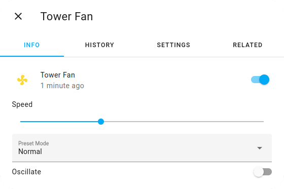
Finally, here is what the corresponding user interface looks like:


Conclusion
I am very happy with the reliability of the final assembly. I have all the power of Home Assistant at my disposal to control it and I have been using it for several months now without any issues. Since then, I've upgraded to a split air conditioning unit and fiddled with automating that too, but that's a story for another time.
Hopefully this article has been useful or interesting to you. If you have any questions, comments or your own experiences to share, please feel free to reach out!
Footnotes
-
Sara Santos (2019). "ESP8266 Pinout Reference: Which GPIO pins should you use?", Random Nerd Tutorials. ↩
-
MQTT Fan Integration, Home Assistant. ↩